

Honors Projects by Members
Here is where our members can showcase their hard work and dedication by posting a description and pictures of their in-progress and finalized Honors Projects.
Semiconductor Manufacturing Simulator
By Mason Sage
The overall objective of this honors project is to go above and beyond the class lecture and its fundamental material, and to delve deeper into the engineering of mechatronic systems. I have brainstormed, designed, prototyped and built an entirely automated machine simulating three essential steps in the semiconductor manufacturing process.
My machine is fully automated using a programmable logic controller to operate the mechanical simulation. This machine will simulate just three steps in the complicated manufacturing process of semiconductors.
The three main simulated microfabrication steps in producing semiconductor wafers will be:
1. Simulating the chemical vapor deposition (CVD) chamber where the silicon dioxide is covered by a monocrystalline or polycrystalline layer of gallium arsenide deposited by vapor at atmospheric pressure in the chamber. This builds up a uniform layer that will layer become covered by a photoresist material, then etched away leaving traces of one layer of the semiconductor.
2. After the wafers have passed through the CVD chamber, they will be transferred to the photolithography stage. Here a silicon wafer is exposed to a layer of light-sensitive polymer called a photoresist. Photoresist is applied though a spin process that coats the wafer evenly as the wafer rotates.
3. After the photoresist is applied, the wafers are transferred to a process of projected printing photolithography. In this process there is a lens with a pattern of the desired layer. The lens blocks UV light (248nm) emitted from behind the pattern. The projected negative pattern is then exposed to the photoresist covered wafer where the photoresist that is exposed to the light is removed and the “shadows” of the pattern lens are left standing which will later shield the material below in an etching stage, which removes any exposed material that was deposited in the CVD chamber. This process repeats many times over again creating a microscopic three-dimensional layered circuit that is the structure of today’s modern integrated circuits.

Automated Semiconductor Manufacturing Simulator By Mason Sage
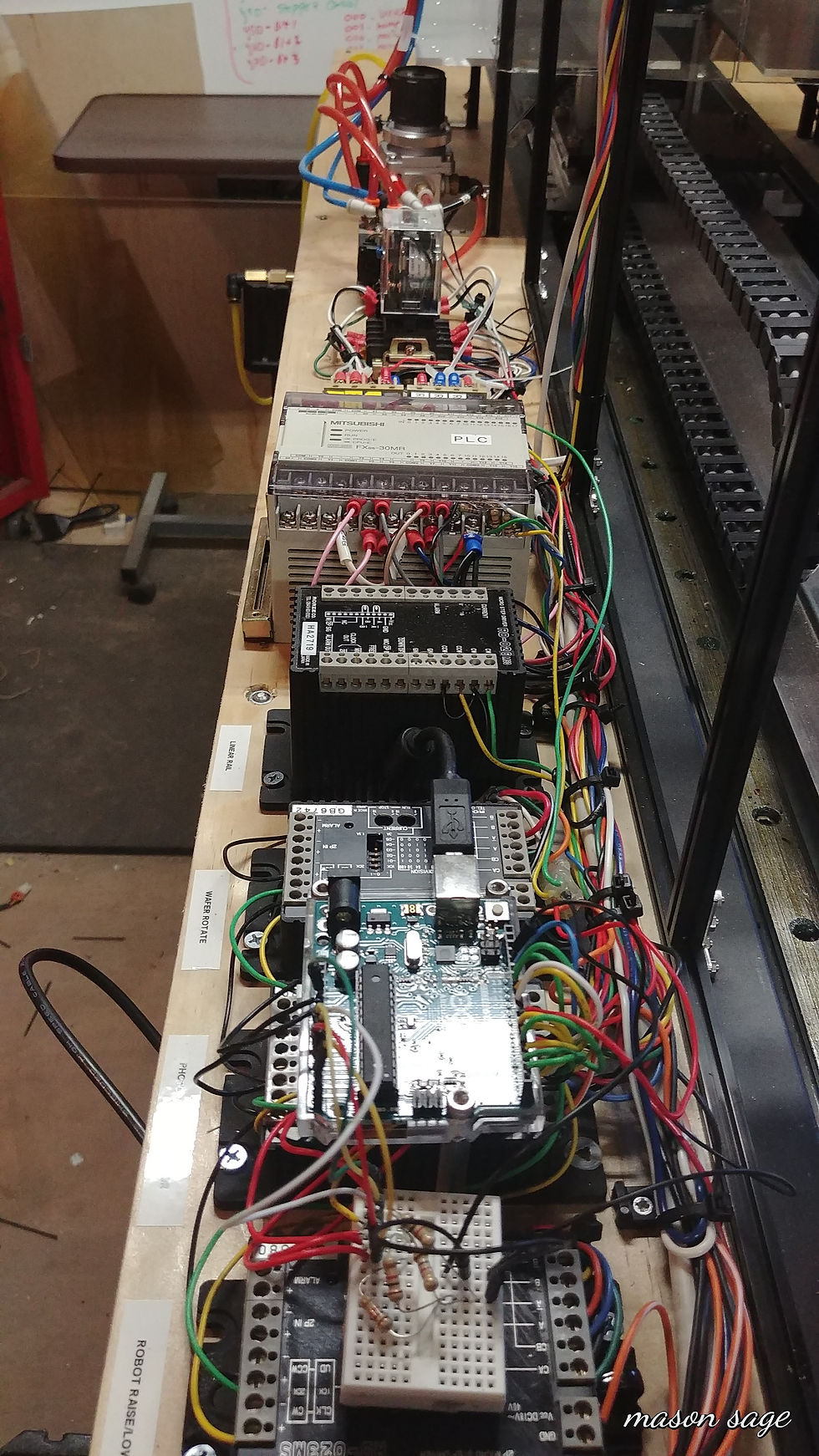
Automated Semiconductor Manufacturing Simulator By Mason Sage

Automated Semiconductor Manufacturing Simulator By Mason Sage
Automated Semiconductor Manufacturing Simulator By Mason Sage
Custom S.C.A.R.A. Robotic Arm (In Progress)
By Mason Sage
The overall objective of this honors proposal is to go above and beyond the class lecture and its fundamental material to explore the complexities of the engineering of mechatronic and robotic systems. I will brainstorm, design, prototype and build a robotic arm classified as a SCARA type utilizing drafting software that is commonly used in all fields of engineering. SCARA (Selective Compliance Assembly Robot Arm) type robotic arms are commonly found in manufacturing due to their reliability and maneuverability. This robotic arm will be built to replicate industry standard robotic arms, in order to do so, the use of computer aided design (CAD) software is needed. I have taught myself Fusion 360, a very powerful industry-leading drafting software. Utilizing this software, my robotic arm will be drafted entirely in parametric modeling. This program not only aids in the design of the arm down to the exact bolt and thread pattern, it also enabled the drafter to create constraints and view the arms degrees of freedom and analyze movement. What sets this software apart from others is its ability to run complex animations of how the project should be assembled or operated. The software also includes analysis on bodies and assemblies such as static stress, modal frequency analysis, thermal analysis, structural buckling, non-linear static stress and most intriguingly, design optimization. After designs are affirmed, Fusion 360 contains integrated Computer Aided Machining (CAM) for 3D printing, or tool pathing for a CNC machine.
My honors project conclusion will include a report of the robotic arm drafted and assembled using CAD, and an industry standard Bill of Material (B.O.M.), analysis of static stress and design optimization. The robotic arm prototype will then be 3D printed using Fusion 360 print environment, then milled out of aluminum using the CAM equipment. The finished arm will be presented to the class and will be shown to complete basic tasks.
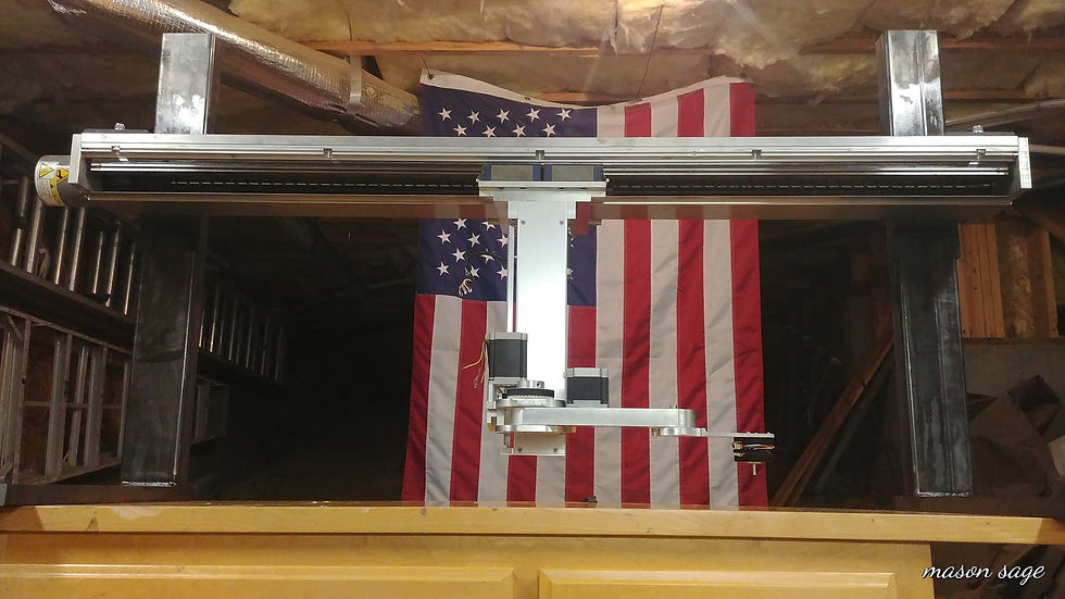
S.C.A.R.A. Robotic Arm

S.C.A.R.A. Robotic Arm

S.C.A.R.A. Robotic Arm
S.C.A.R.A. Robotic Arm